
SpiruSense
Intelligent Photobioreactor for Spirulina Cultivation and Monitoring
Intelligent Photobioreactor for Spirulina Cultivation and Monitoring
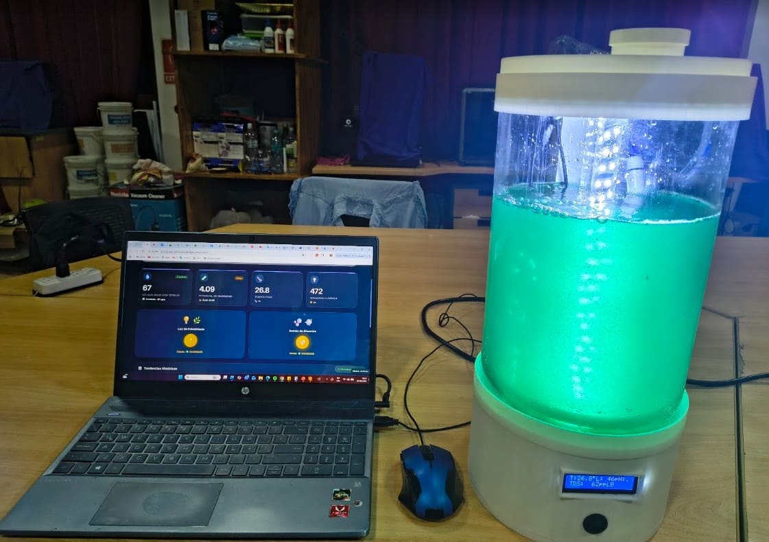
Img. 1: SpiruSense, intelligent photobioreactor.
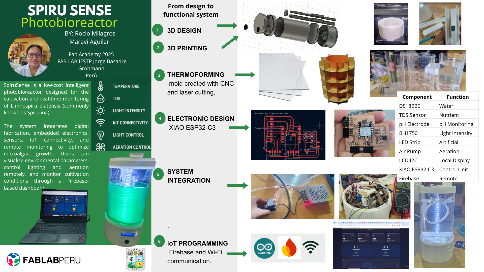
SpiruSense is an intelligent photobioreactor for the cultivation and monitoring of spirulina.
It was developed as my Fab Academy final project and integrates digital fabrication, sensors, electronics, embedded programming, and the Internet of Things.
presentation.mp4 – Complete demonstration of the fabrication, integration, and operation of SpiruSense.
Final presentation video: presentation.mp4
presentation.png – Summary slide of the SpiruSense system.
Final presentation slide: presentation.png
Cultivating microalgae with digital fabrication, sensors, and the Internet of Things.
The idea for SpiruSense emerged from the need to improve the traditional spirulina cultivation methods used in the laboratory, where recycled PET bottles and manual monitoring are commonly used.
Although this method works, it has limitations such as the lack of real-time control, absence of data recording, difficulty controlling lighting, limited automation, and dependence on constant supervision.
Initially, I considered developing a submerged liquid fermentation bioreactor for Trichoderma or an intelligent culture collection system for microalgae. However, after analyzing the possibilities of integrating the skills learned during Fab Academy, I decided to evolve the idea into an intelligent photobioreactor.
This is how SpiruSense was born: a system that integrates digital fabrication, electronics, sensors, programming, and IoT to monitor and control the cultivation of Limnospira platensis, commonly known as spirulina.
Img. 2: Prototype created with AI - ChatGPT.
Img. 3: Prototype created with AI - ChatGPT.
SpiruSense is an intelligent photobioreactor designed for the cultivation and monitoring of spirulina. Its main objective is to improve the monitoring of culture conditions through sensors, local visualization, and remote monitoring.
The system measures important variables such as temperature, pH, total dissolved solids, and light intensity. In addition, it allows remote control of the lighting and aeration of the culture through a platform connected to Firebase.
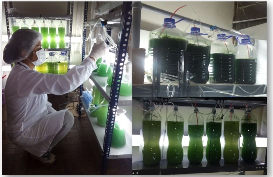
Img. 4: Current spirulina cultivation method.
| Photo | Component | Description | Use in the Project |
|---|---|---|---|
|
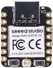
XIAO ESP32-C3 | Microcontroller with integrated WiFi and Bluetooth connectivity. | Main unit responsible for reading sensors, processing data, and communicating with Firebase. |
|
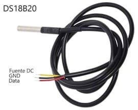
DS18B20 Sensor | Waterproof digital temperature sensor. | Monitoring the temperature of the spirulina culture. |
|
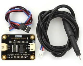
Gravity TDS Sensor | Sensor for measuring total dissolved solids. | Estimation of salts and nutrients concentration in the culture medium. |
|
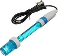
pH E201-C BNC Electrode | Analog electrode for pH measurement. | Control of the acidity or alkalinity level of the culture. |
|
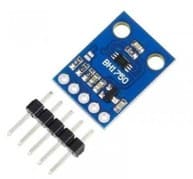
BH1750 Sensor | Digital light intensity sensor based on I2C. | Measurement of light available for spirulina growth. |
|
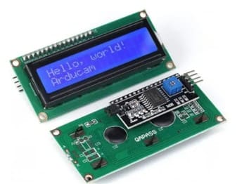
16x2 I2C LCD Screen | Alphanumeric display for local visualization. | Displays temperature, pH, TDS and light intensity in real time. |
|
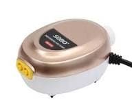
Air Pump | Continuous aeration system. | Maintains culture circulation and oxygen transfer. |
|
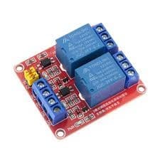
2-Channel Relay Module | Electronic switching module. | Controls lighting and aeration remotely. |
|
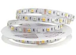
White LED Strip | Artificial lighting source. | Provides light for photosynthesis. |
|
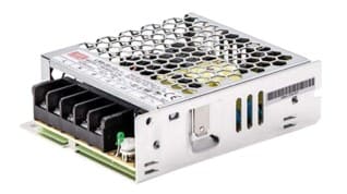
12V Power Supply | DC power source. | Main power supply for the entire system. |
|
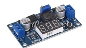
LM2596 Step-Down | Adjustable DC-DC converter. | Voltage regulation for electronic components. |
|
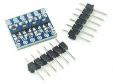
5V–3.3V Logic Converter | Bidirectional logic level adapter. | Ensures safe communication between devices. |
|
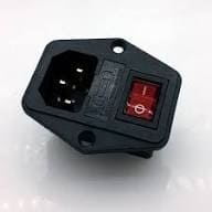
ON/OFF Switch | Main power switch. | Turns the complete system on and off. |
|
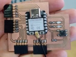
Custom PCB | Custom electronic board designed and fabricated during Fab Academy. | Integrates sensors, actuators and the microcontroller. |
During the development of the project, different design options were evaluated. The first idea was to build a bioreactor for Trichoderma, but this required sterility conditions, mechanical agitation, and more complex microbiological validation.
Later, I considered an intelligent microalgae culture collection system, but this option had less system integration and did not allow me to fully demonstrate the skills developed during Fab Academy.
Finally, I chose to develop an intelligent photobioreactor because it allowed me to integrate 2D and 3D design, additive fabrication, subtractive fabrication, custom electronics, sensors, embedded programming, WiFi communication, IoT, and system integration.
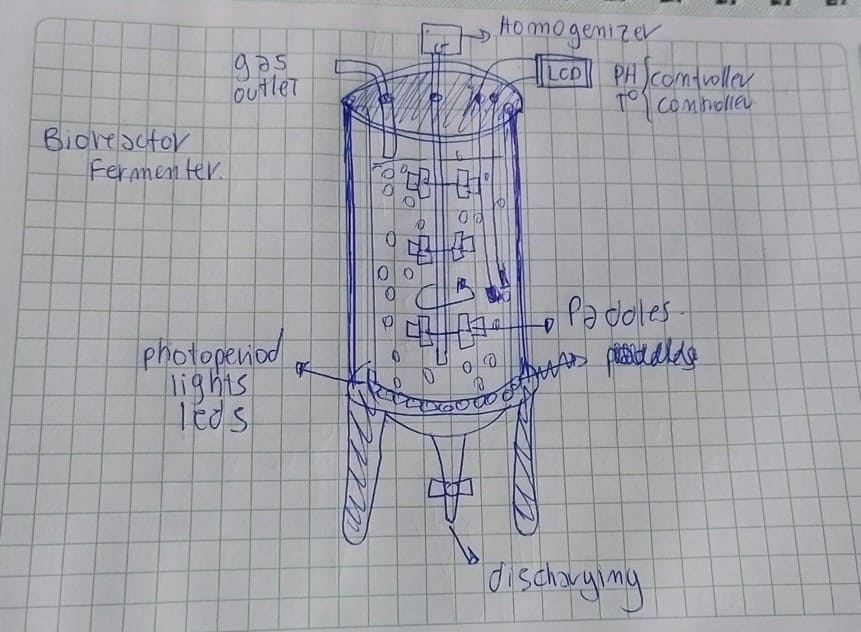
Img. 19: Initial bioreactor idea with paddles.
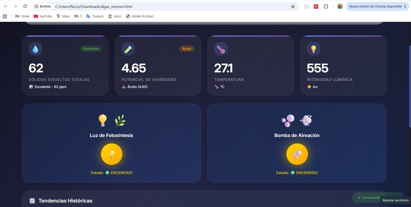
Img. 20: Real-time monitoring.
The following table summarizes the main components used in SpiruSense, including their quantity and use within the system.
| Component | Quantity | Total Cost (S/.) | Total Cost (USD) | Use in the Project |
|---|---|---|---|---|
| XIAO ESP32-C3 | 1 | 40.00 | 11.11 | Main microcontroller. |
| DS18B20 Sensor | 1 | 5.50 | 1.53 | Temperature measurement. |
| TDS Sensor | 1 | 75.00 | 20.83 | Dissolved solids measurement. |
| pH E201-C BNC Sensor | 1 | 65.00 | 18.06 | pH measurement. |
| BH1750 Sensor | 1 | 10.00 | 2.78 | Light intensity measurement. |
| I2C LCD Screen | 1 | 25.00 | 6.94 | Local visualization. |
| Air Pump | 2 | 36.00 | 10.00 | Culture aeration. |
| Relay Module | 2 | 20.00 | 5.56 | Lighting and aeration control. |
| LED Strip | 1 | 5.00 | 1.39 | Culture lighting. |
| 12V Power Supply | 1 | 60.00 | 16.67 | Main power supply. |
| LM2596 Step-Down Regulator | 1 | 5.00 | 1.39 | Voltage conversion. |
| 5V–3.3V Logic Converter | 1 | 6.00 | 1.67 | Signal adaptation for pH sensor. |
| ON/OFF Switch | 1 | 5.00 | 1.39 | General power on/off. |
| Transparent Acrylic | 1 | 60.00 | 16.67 | Thermoformed cylinder. |
| PLA Filament | 1 | 75.00 | 20.83 | 3D printing of the structure. |
| PCB and Electronic Components | 1 | 50.00 | 13.89 | Custom electronic board. |
| Resistors and Connectors | Several | 10.00 | 2.78 | Circuitry and connections. |
| Miscellaneous Materials | Several | 30.00 | 8.33 | Cables, hoses, screws, and sealing. |
| Estimated Total | S/ 582.50 | USD 161.81 | ||
The estimated total cost of the prototype was approximately S/ 582.50, equivalent to USD 161.81, not including the use of Fab Lab machines or the hours of design, fabrication, and programming.
From concept to final integration, SpiruSense was developed through several stages of design, fabrication, testing, and redesign.
| Functionality | Description | Validation |
|---|---|---|
| Temperature monitoring | DS18B20 sensor reading. | Reading tests on LCD and Firebase. |
| pH monitoring | E201-C BNC electrode reading. | Calibration tests with buffer solutions. |
| TDS monitoring | Dissolved solids reading. | Tests in liquid medium. |
| Light measurement | BH1750 sensor reading. | Light intensity tests. |
| LCD screen | Local visualization of parameters. | Real-time data displayed. |
| WiFi communication | ESP32-C3 internet connection. | Data sent to Firebase. |
| Lighting control | Remote LED activation. | On/off control from the platform. |
| Aeration control | Remote pump activation. | Remote control through Firebase. |
The project began with the question: how can spirulina cultivation be improved using digital fabrication and IoT?
Based on this question, initial sketches were made and the general structure of the photobioreactor was designed. The design had to contain the culture, integrate sensors, house the electronics, allow the passage of hoses and cables, and maintain an appearance close to a finished product.
The structure was modeled in Fusion 360, considering:
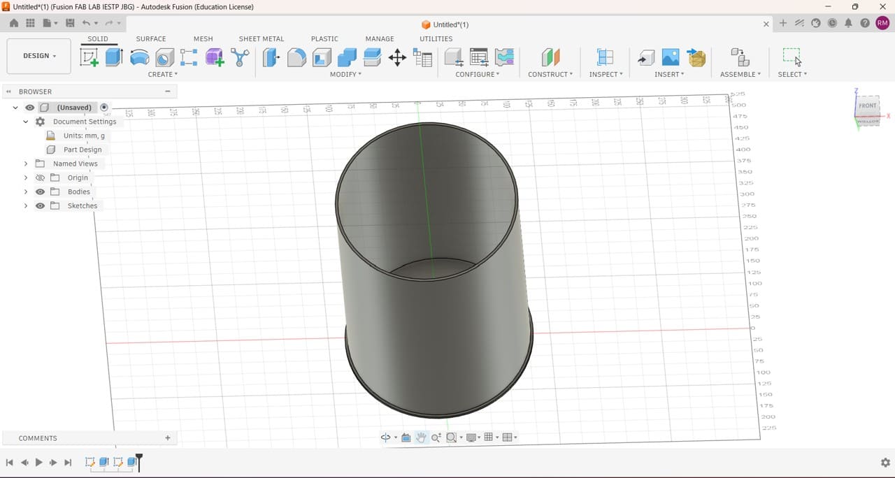
Img. 21: Initial design in Fusion 360.
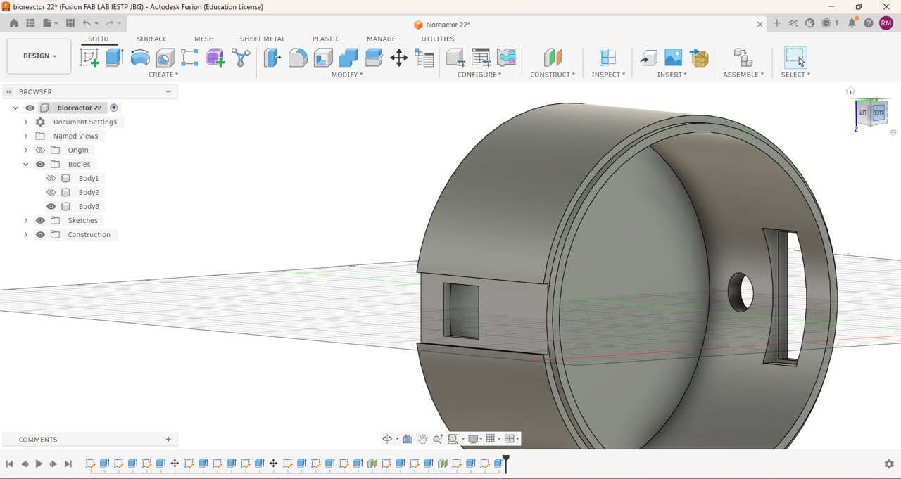
Img. 22: Design of the base that contains the electrical system.
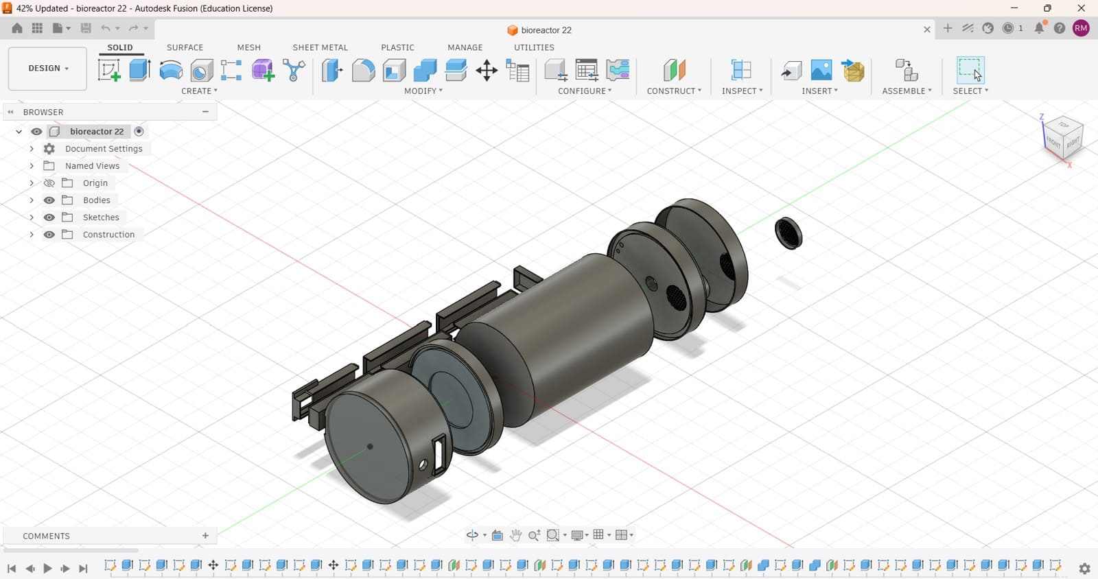
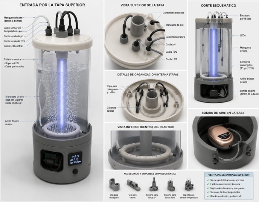
Img. 23: Final photobioreactor design.
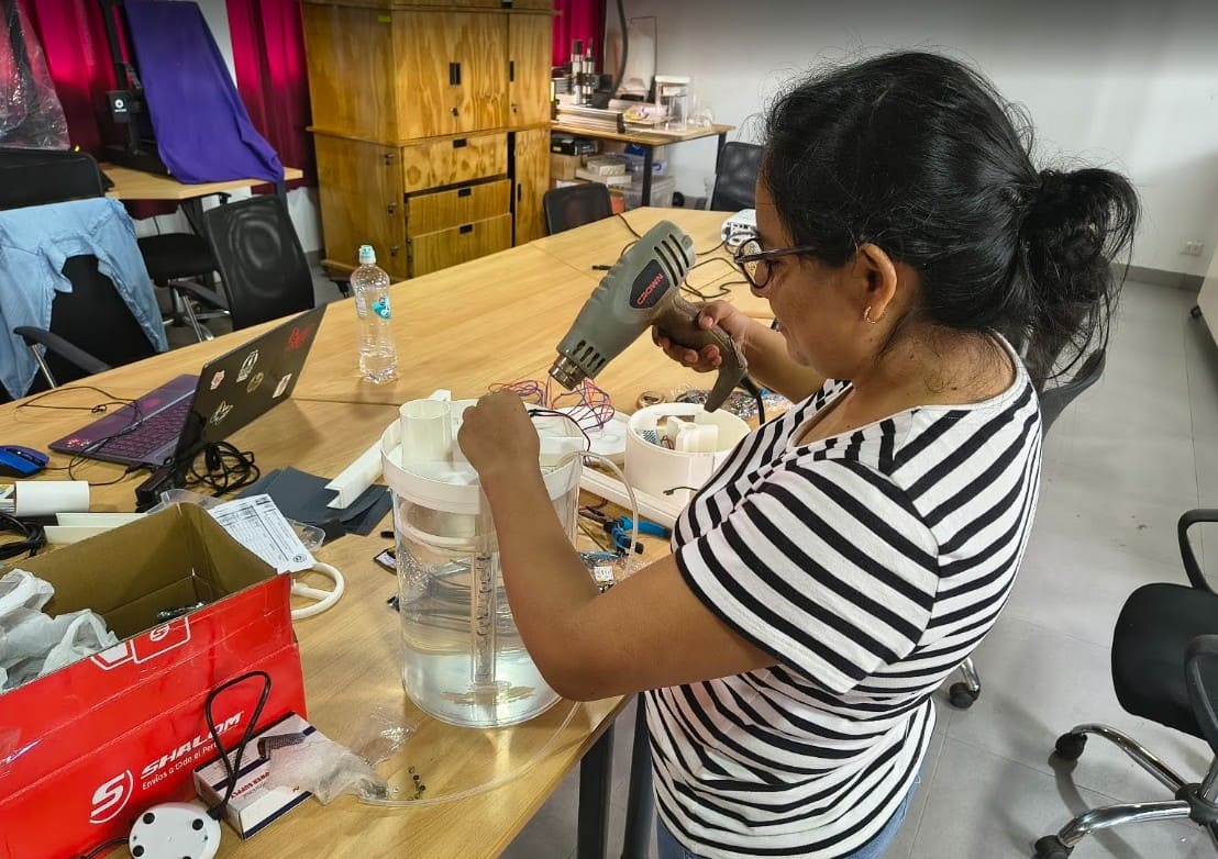
The base, lid, central column, and aeration system were fabricated by 3D printing using PLA.
The transparent cylinder was fabricated by thermoforming acrylic. For this, a mold made with laser cutting and CNC was used. This process required several attempts until a functional shape was obtained, because the first tests showed deformations.
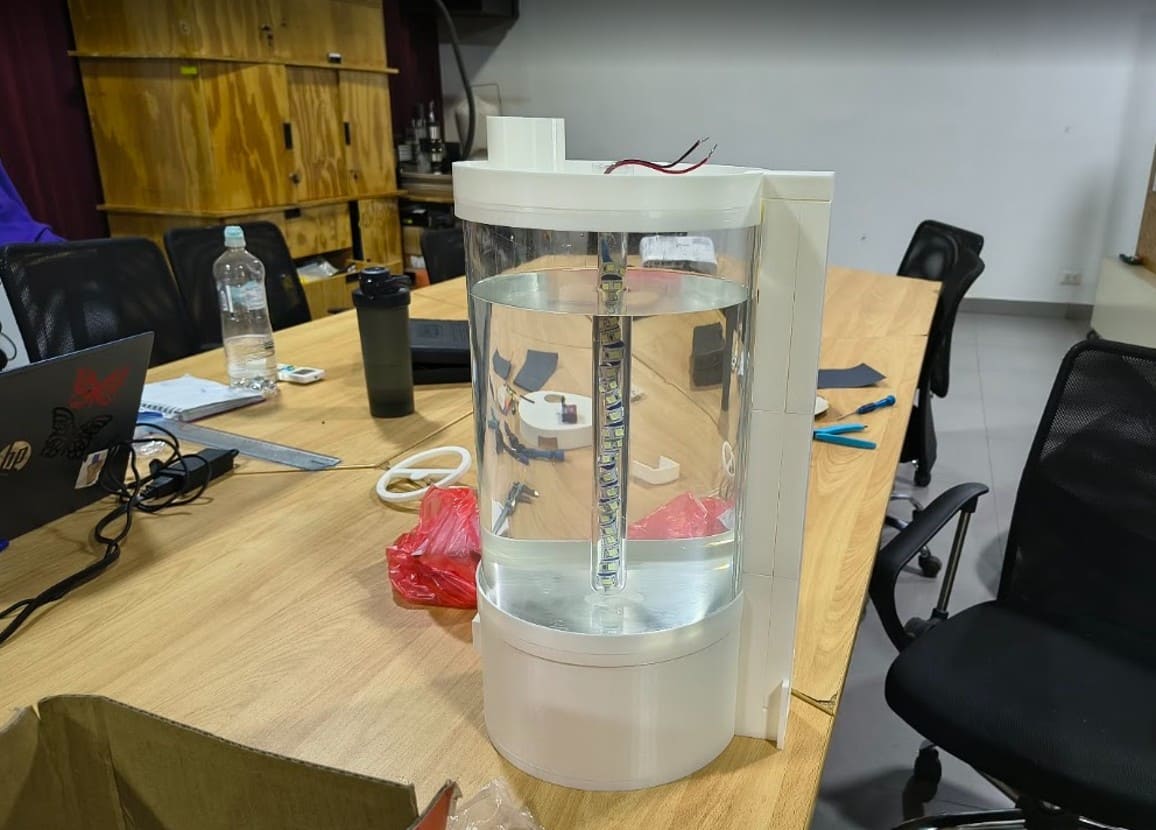
The result was a transparent acrylic cylinder that allows the culture to be observed and houses the internal lighting system.
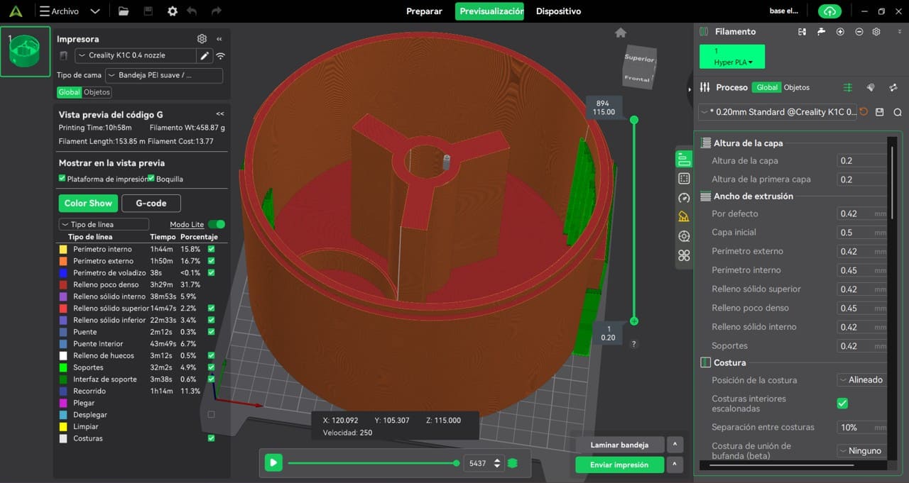
Img. 24: Adjustment of PLA printing parameters.
Img. 25: 3D printed parts.
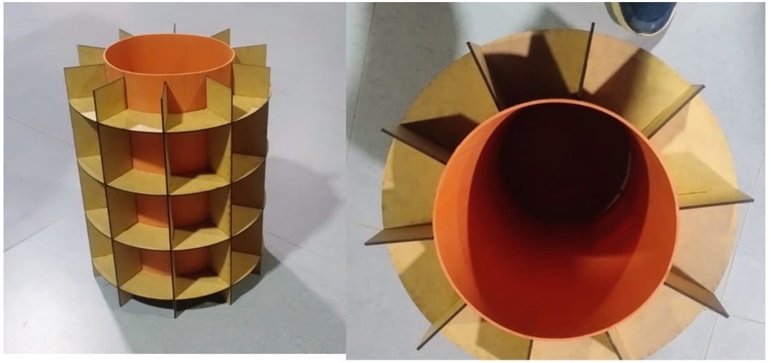
Img. 26: Mold for thermoforming.
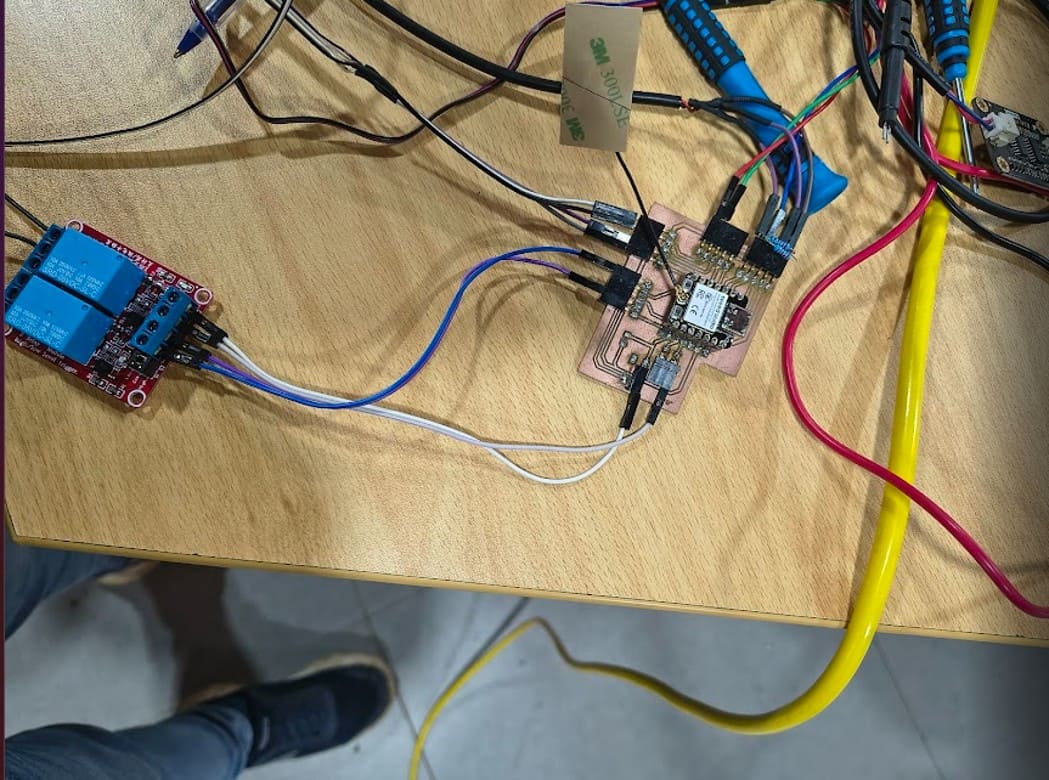
The electronic system was designed in KiCad and fabricated by PCB milling. The board was designed to integrate the XIAO ESP32-C3 and facilitate the connection of sensors and actuators.
During assembly, connectors, resistors, and electronic components were soldered. Later, continuity and operation tests were performed.
Although some problems appeared during the first tests, the board worked correctly and allowed the monitoring and control system to be integrated.
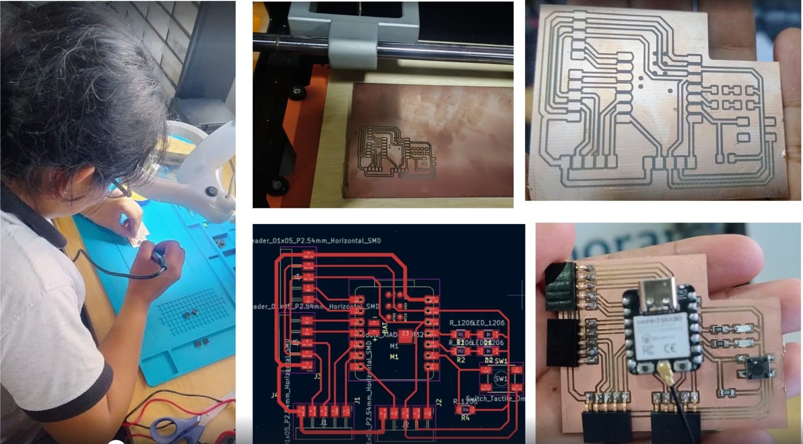
Img. 27: PCB design process.
The programming was done in Arduino IDE. The firmware allows the system to:
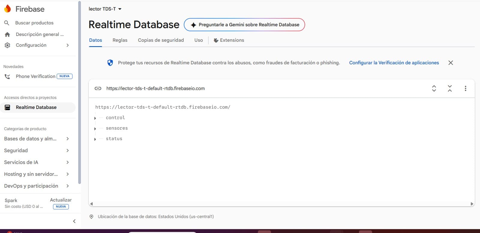
Firebase was used as the IoT platform for real-time remote monitoring and system control.
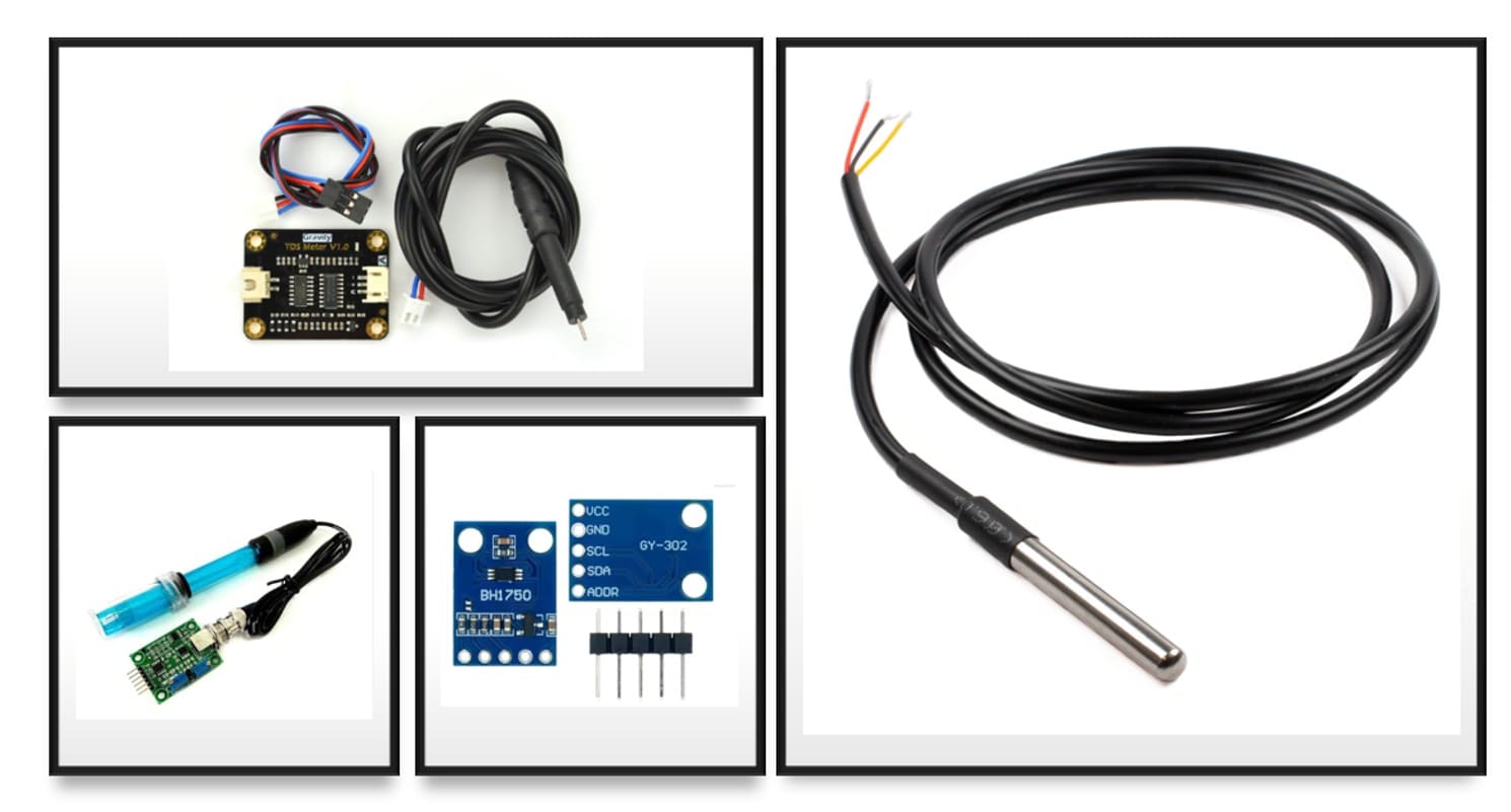
Img. 28: Sensors used.
Img. 29: Integrated board with sensors.
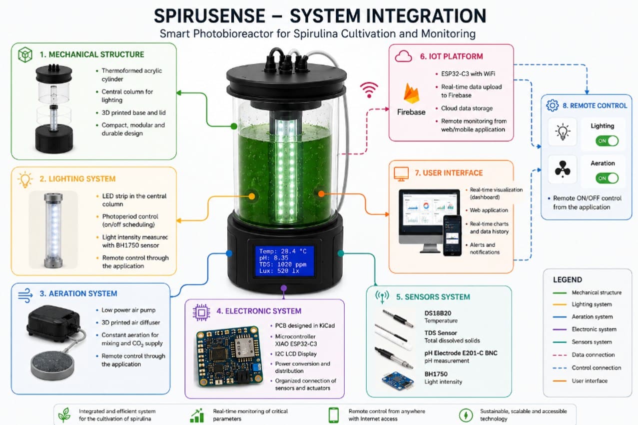
System integration was one of the most important stages. All subsystems had to work together:
During this stage, leak tests, sensor tests, connectivity tests, and general operation tests were performed.
Img. 30: Firebase integration for real-time monitoring.
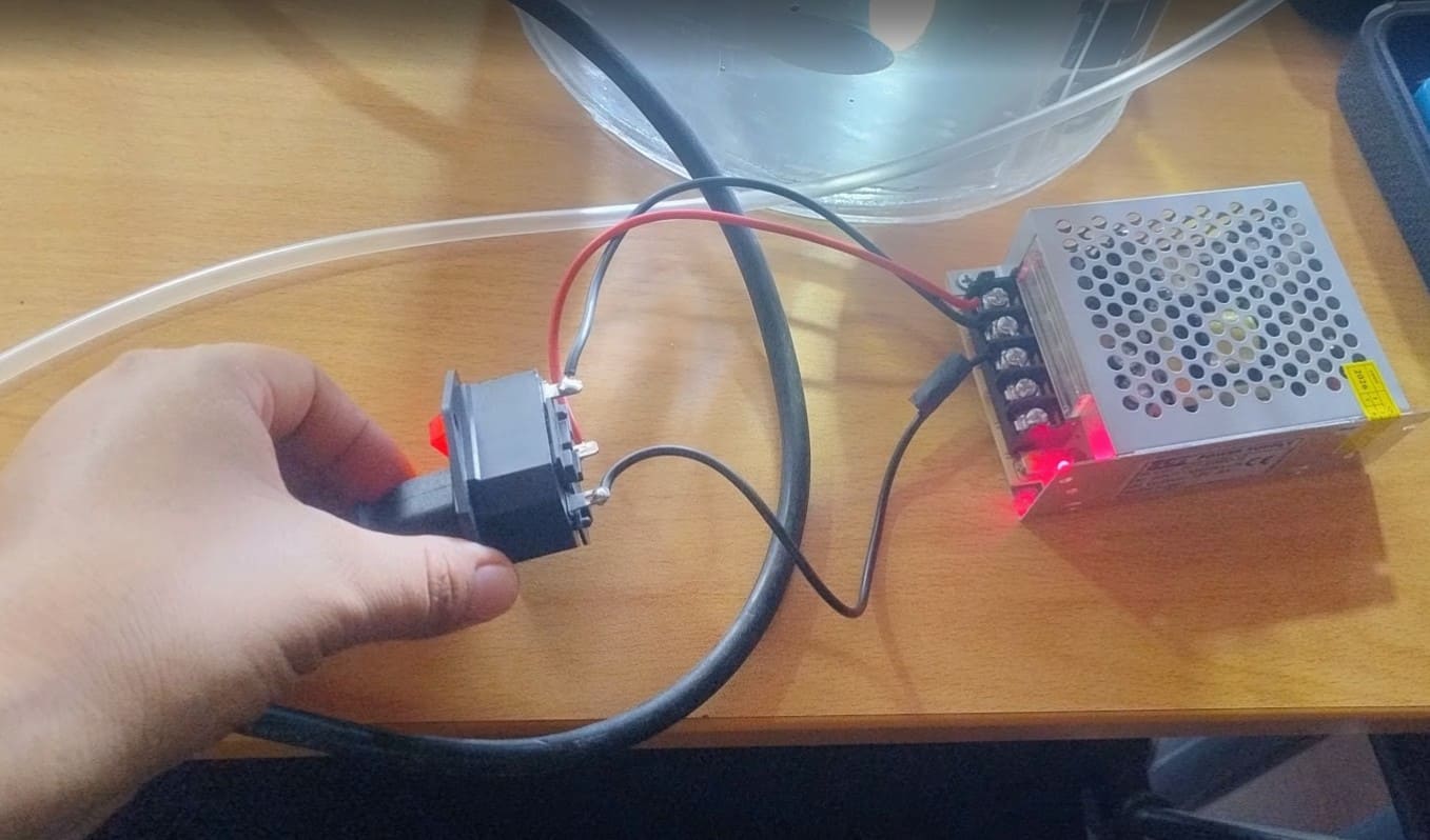
Img. 31: Power integration.
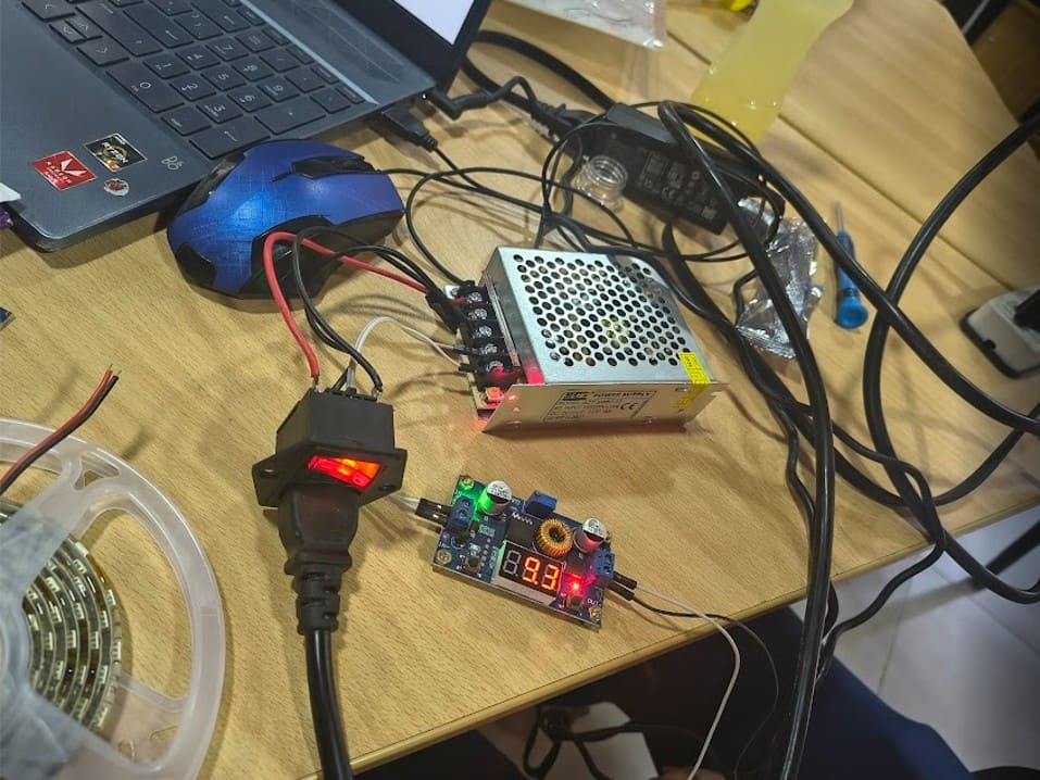
Img. 32: Voltage regulator integration.
Img. 33: Integration of lights and air pump.
Img. 34: Avoiding short circuits with heat-shrink tubing.
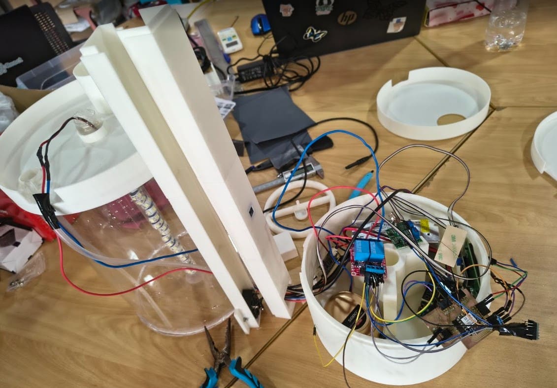
Img. 35: Integrated system; cable organization stage.
| Phase | Start | End | Status |
|---|---|---|---|
| Initial research | March | March | Completed |
| Idea definition | March | April | Completed |
| CAD design | April | May | Completed |
| Electronic design | May | May | Completed |
| PCB fabrication | May | May | Completed |
| 3D printing of structure | May | June | Completed |
| Acrylic thermoforming | June | June | Completed |
| Sensor integration | June | June | Completed |
| Firebase integration | June | June | Completed |
| Functional tests | June | June | Completed |
| Final video and slide | June | June | Completed |
| Final presentation | June | June | Completed |
| Problem | Cause | Solution |
|---|---|---|
| Initial LEDs failed. | The silicone coating was deteriorated. | The LED strip was replaced. |
| Photoresistor burned. | Incorrect 5V power supply. | The power supply was corrected to 3.3V. |
| pH calibration was complicated. | Lack of buffer solutions. | CITE Productivo Madre de Dios provided buffer solutions. |
| WiFi problems. | Unstable network. | Mobile hotspot was used. |
| Irregular aeration. | Inefficient initial design. | The diffuser was redesigned three times. |
| I2C conflicts. | LCD and light sensor shared the same bus. | Programming and addressing were adjusted. |
| Failed thermoforming. | Temperature and time were not optimal. | Tests were repeated until the cylinder was obtained. |
The final version of SpiruSense was tested with the system completely integrated.
The photobioreactor was able to:
SpiruSense demonstrates how digital fabrication can be applied to the development of biotechnological solutions. The project allowed me to integrate CAD design, 3D printing, thermoforming, custom electronics, programming, and IoT into a single functional system.
The development of the project showed that system integration is one of the most challenging stages, since it is not enough for each component to work separately: all components must work together inside a real physical structure.
SpiruSense by Rocío Milagros Maraví Aguilar is licensed under a Creative Commons Attribution-NonCommercial-ShareAlike 4.0 International License (CC BY-NC-SA 4.0).
This license allows other people to study, modify, and improve the project for educational and research purposes, as long as the original authorship is recognized, it is not used for commercial purposes without authorization, and new versions are shared under the same license.
The development of SpiruSense was carried out progressively throughout Fab Academy. The following assignments directly contributed to the design, fabrication, programming, integration, and validation of the final project.